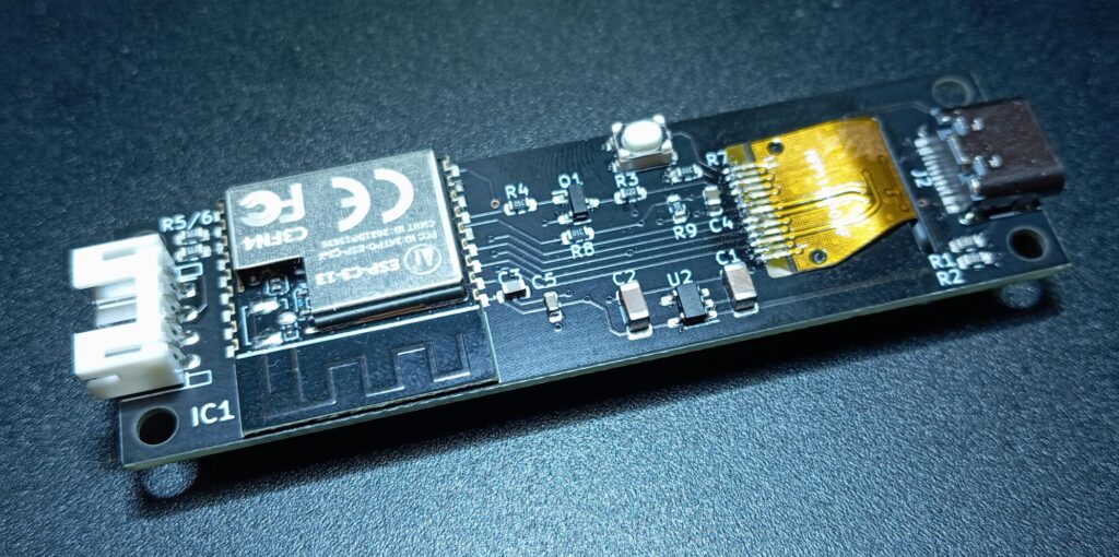
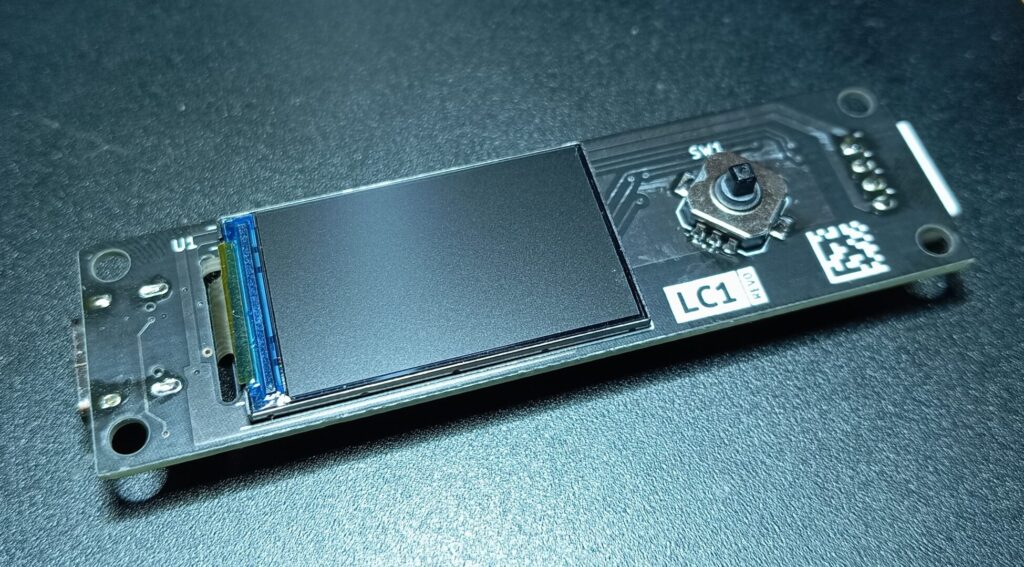
After the boards had been lying around unassembled for a year, it was time to solder the components and run a simple program as a test.

The components on the underside could be quickly soldered with a hotplate. Only the flat flex cable and the 2 mm plug for connecting the LEDs had to be soldered by hand.

All that remains is to solder the small 5-way joystick to the top of the board and we’re done. The board can be fitted with a 0.96 inch IPS display with 80×160 pixels or a 1.14 inch display with 135×240 pixels. An ST7789 is used as the controller. For the first test, however, we will not control the display.
#include "FastLED.h"

#define NUM_LEDS  50    // Enter the total number of LEDs on the strip
#define PIN 21   // The pin connected to Din to control the LEDs

CRGB leds[NUM_LEDS];

void setup() {
  FastLED.addLeds<WS2812, PIN, RGB>(leds, NUM_LEDS).setCorrection(TypicalLEDStrip);
  FastLED.setMaxPowerInVoltsAndMilliamps(5, 1500);  // Set power limit of LED strip to 5V, 1500mA
  FastLED.clear();  // Initialize all LEDs to "off"
}

void loop() {
  rainbowCycle(20);
}

void rainbowCycle(int DelayDuration) {
  byte *c;
  uint16_t i, j;

  for(j=0; j < 256; j++) {
    for(i=0; i < NUM_LEDS; i++) {
      c = Wheel(((i * 256 / NUM_LEDS) + j) & 255);
      leds[NUM_LEDS - 1 - i].setRGB(*c, *(c+1), *(c+2));
    }
    FastLED.show();
    delay(DelayDuration);
  }
}

byte *Wheel(byte WheelPosition) {
  static byte c[3];

  if(WheelPosition < 85) {
   c[0] = WheelPosition * 3;
   c[1] = 255 - WheelPosition * 3;
   c[2] = 0;
  }
  else if(WheelPosition < 170) {
   WheelPosition -= 85;
   c[0] = 255 - WheelPosition * 3;
   c[1] = 0;
   c[2] = WheelPosition * 3;
  }
  else {
   WheelPosition -= 170;
   c[0] = 0;
   c[1] = WheelPosition * 3;
   c[2] = 255 - WheelPosition * 3;
  }

  return c;
}
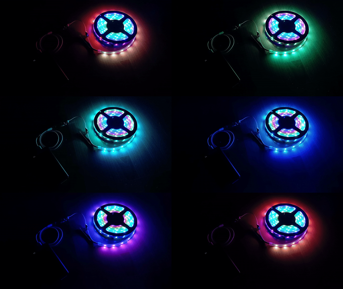
The board can be programmed and supplied with power directly via USB. The example program above uses the FastLED library to create a rainbow that runs through the LEDs.

Leave a Reply