In recent years, Zigbee has become widely used in home automation. A number of manufacturers offer devices that communicate with each other via Zigbee. A central hub or gateway almost always plays a role here, which takes over the coordination and at the same time enables a connection to the network. For maximum flexibility and compatibility, it is advisable to implement such a gateway yourself using open software such as Zigbee2MQTT. To communicate with the various devices, this only requires a Zigbee transceiver. A Raspberry Pi offers a space and power-saving option for this. Together with a add-on board equipped with an appropriate transceiver, like the one presented here, a compact gateway is created.

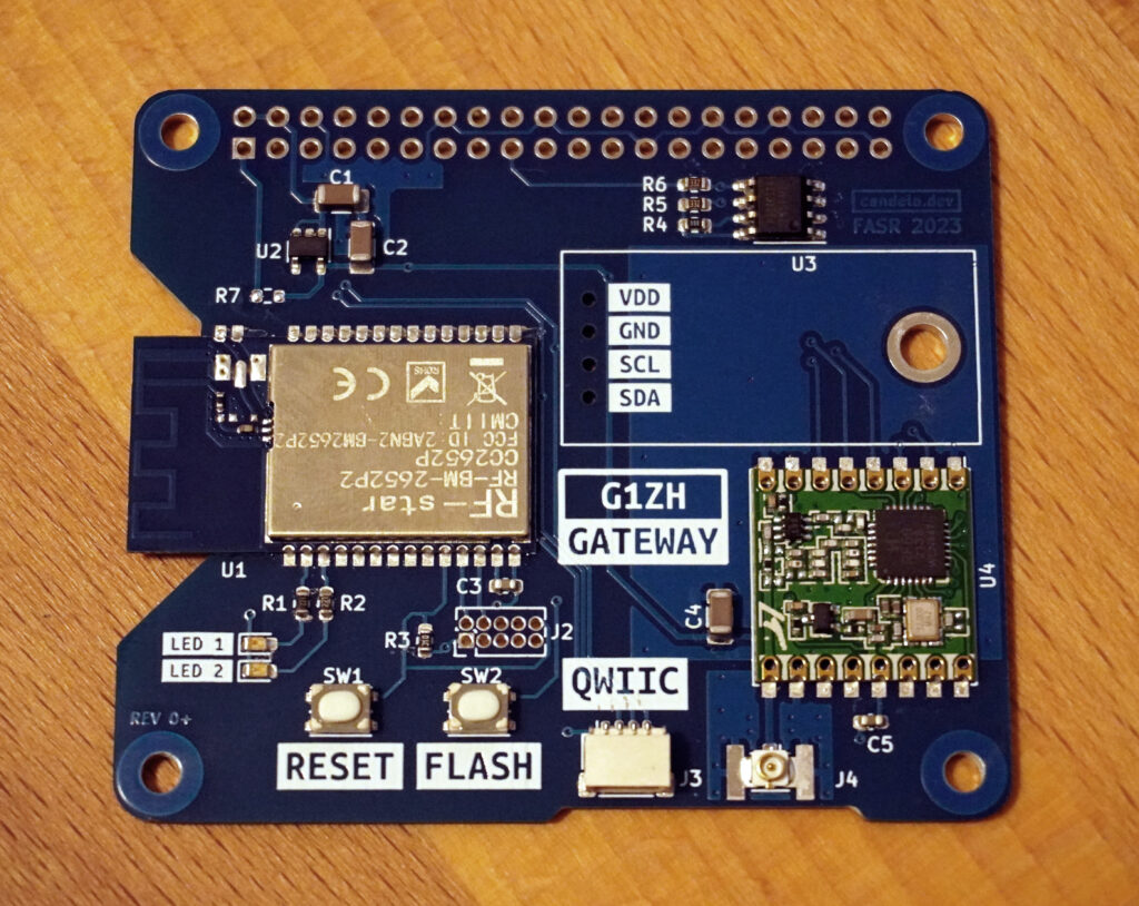
There is a range of Zigbee transceivers. The CC2652/CC1352 series from Texas Instruments are supported by Zigbee2MQTT. The CC2652 therefore also forms the heart of the board. The actual chip is already implemented on a module with all the components required for operation. This means that the module (U1) only requires a few external components. In addition to a RESET button (SW1) and a button which is required to initiate a firmware update (SW2), only two status LEDs are connected. Communication with the Raspberry Pi takes place via the serial port.

The connection to the Raspberry Pi ish made via the standard 2×20 connector (J1). The firmware update for the Zigbee module is carried out via the serial interface. In addition, its JTAG interface is also available on J2. To connect I²C devices, these signals are available both on a qwiic connector and on the J5 connector.
Assembly options
Equipped with the components described above, the board still has plenty of space available. This was mainly used for an additional radio module, which is optional.

The 3.3 volt power supply for the wireless modules can be provided by the Raspberry Pi. In this case, the 0-Ohm resistor R7 must be fitted. Alternatively, the 3.3 volts can also be generated via a linear regulator (U2) from the main supply voltage.
Expansion boards are called HATs on the Raspberry Pi. According to the specification, an ID EEPROM (U3) can be connected to pins 27 and 28 (ID_SD and ID_SC) which contains further information about the board.

The RFM69HCW module or the pin-compatible RFM95W/96W/98W modules, which are also capable of LoRa modulation, can be fitted as an optional radio module. Communication takes place via SPI. RESET and the GPIOs (DIO0-DIO2) are also connected to the Raspberry Pi. An IPEX connector or an SMA edge connector can be used to connect the antenna. The additional radio module also enables communication with devices in other radio spectrums.
PCB
At 56 mm x 56.5 mm, the two-layer board complies with the specification for Raspberry Pi HATs. The connector (J5) is located on the underside, but an I²C module with a standard 2.54 mm header can be connected via four holes. A spacer nut soldered to the board allows the fastening of such a module.

The board is assembled using the vapor phase soldering method, which produces excellent results. Only the connectors J1 and J5 still have to be soldered by hand.
In the next part of this series, we will put the board into operation and create the basis for operating the Zigbee module by installing Zigbee2MQTT and an MQTT server. And we will connect the first Zigbee devices.
Leave a Reply